
ENGINEERS BEWARE: API vs ASME Relief Valve Orifice Size

Many are not aware of the major differences between the orifice sizes and discharge coefficients suggested by the API and the actual, ASME values used by the relief valve vendors. According to API-520, Part 1, the API orifice sizes and discharge coefficients are assumed values and are to be used only for the initial selection of the relief valve. They were developed to facilitate choosing a relief valve size early in a project and to ensure that the relief valve finally purchased will have a certified capacity that meets or exceeds the required relief capacity.
However, the differences in capacity between the initial choice of API orifice and the actual ASME orifice can be significant. For most projects, the actual ASME orifice can provide a much greater flowrate. When one also considers the following:
Conservatisms in estimating the required relief loads;
Calculated orifice sizes are usually between the standard, letter designated API sizes. When this occurs, the next larger orifice size is chosen resulting in the valve being oversized with just an API orifice;
The certified ASME discharge coefficient is derated by a factor of 0.9 resulting in another potential source of over design;
the final, purchased, relief valve can be greatly oversized.
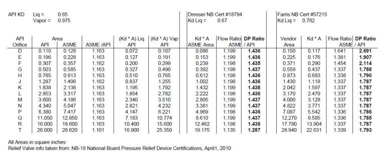
The attached table, compares just the differences between orifice designs for two relief valves versus an initial, API design. The first column is the API letter designation for the orifice, followed by the API and then the ASME orifice areas in the next two columns. The fourth column shows that, just based on orifice size, except for the “T” orifice, the ASME orifice flow area is about 16% higher than the API area.
One also needs to consider differences in valve discharge coefficients. Columns 5 and 6 show the (A * Kd) API values. Note that one should not mix and match the orifice areas and discharge coefficients. The API Kd should only be used with the API area – the same with ASME values.
Two actual relief valves are compared in the table. One is a Dresser liquid relief design with orifice areas the same as the ASME designated ones. Since many vendors have valves with areas different than ASME, the second valve is a Farris liquid relief design with orifice sizes as shown. The certified discharge coefficients are also shown for both valves.
The table shows the Farris valve to have a flowrate about 20% higher than the API valve for all sizes except “T”. It also shows the flowrate from the Farris valve can be higher by as much as 64% for a “D” orifice. The columns next to the flow ratio for both valves show estimated pressure drop ratios which were taken just as the flow ratios squared.
PROCESS ENGINEERS BEWARE!
As shown, the actual pressure drops for the Dresser valve, using actual flow capacity can be higher than those estimated with the API flow capacity by about 44%. But, with the Farris valve, the pressure drop could be higher by a factor of 2.7! And this does not account for conservatisms in estimating the relief load, extrapolation to larger orifice sizes, or derating of the discharge coefficient.
If not recognized early in a project, both the inlet and outlet relief valve piping could be significantly undersized as well as any downstream relief valve outlet disposal facilities (flare, scrubber, catch tank, etc.). Issues with acoustically induced and flow induced vibration of the piping may be missed. Emissions from the disposal facilities could also be underestimated, potentially undermining any early permitting activities. All of these could result in a significantly higher capital cost for the project if not captured early.
Consideration should be made to using the ASME orifice sizes during front end engineering.